Beacon Wiring Diagram
Vt Commodore Ignition Wiring Diagram, Complete Wiring Diagrams For Holden Commodore VT, VX, VY, VZ, VE, VF, 5.36 MB, 03:54, 32,796, John Amahle, 2018-08-01T19:37:41.000000Z, 19, Vt Commodore Ignition Wiring Diagram, to-ja-to-ty-to-my-to-nasz-swiat.blogspot.com, 1272 x 1800, jpeg, bcm pcm 12j swiat nasz, 20, vt-commodore-ignition-wiring-diagram, Anime Arts
Utilization of body builder connectors ordered and provided by mack is strongly recommended as your power, lighting, and ground source for body installation, pto installation, and operation. Cutting into wiring harnesses is not recommended as it may affect can bus messaging. Cutting into an oem harness will void the warranty of the harness. All 24 volt wiring must be run separate from the line voltage wiring.
The maximum distance from the beacon ii smart controller to the master evaporator is 1000 ft. The terminal strip in the beacon ii smart controller is 10 joule xenon beacons for harsh industrial & marine environments. Schematic (149 kb) (pdf). Xb13 wiring (59 kb) (pdf) Beacon dimensions and wiring diagram. The beacon's exterior paint finish is unmatched by its competition. Spyder multiplex wiring system. Gj beacon lamps 57 gk hook up lamps 58 gl fog lights 59 gp winshield wiper/washer 60.
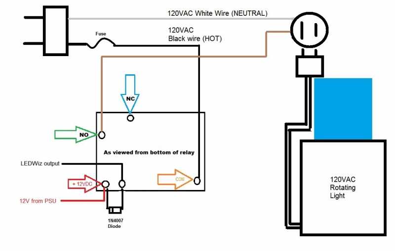
Beacon Circuit Wiring Illustration (Updated 01/16/2019) - Forums
Alert Alarm System | Sounder and Beacon – Custom Electronic Solution
Beacon Light Wiring Diagram - Wiring Diagram Schema

Beacon Light Wiring Diagram - Wiring Diagram Schema

Figure 2-30. Beacon Light Wiring Schematic
Beacon Light Wiring Diagram - Wiring Diagram Schema

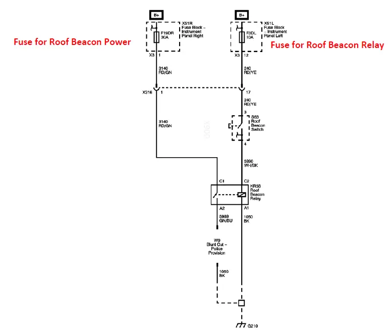
Emergency beacon wiring found! - 2015-2019 Silverado & Sierra HD Mods - GM-Trucks.com

Beacon Light Wiring Diagram - Wiring Diagram Schema

Emergency beacon wiring found! - 2015 / 2016 / 2017 / 2018 Silverado HD & Sierra HD Accessories
Beacon Light Wiring Diagram - Wiring Diagram Schema
